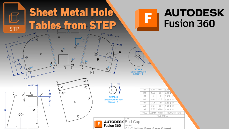
A question was recently asked on the forums about creating hole tables from a flat sheet metal component. The trick, though, is that the component is a STEP file, or comes from other software such as Inventor or SolidWorks.
I’ve previously documented a workflow for non-sheet metal parts here, which is much simpler. With Sheet Metal, there is an extra step of 2, as you need to navigate between capturing and not capturing design history.
Below is a quick video showing the workflow.

You must be logged in to post a comment.