Guest Post by Jhoel Forshav
Since this is my first guest blog post on the Unofficial Inventor blog, I’d like to thank Clint Brown for inviting me to do this. Those of you who visit the Inventor Customization Forum from time to time may have seen my name before, as I’m a very active in responding to posts there. Therefore, it’s no coincidence that the challenge I’ll be taking on in this blog post was originally posted by a user of the forum.
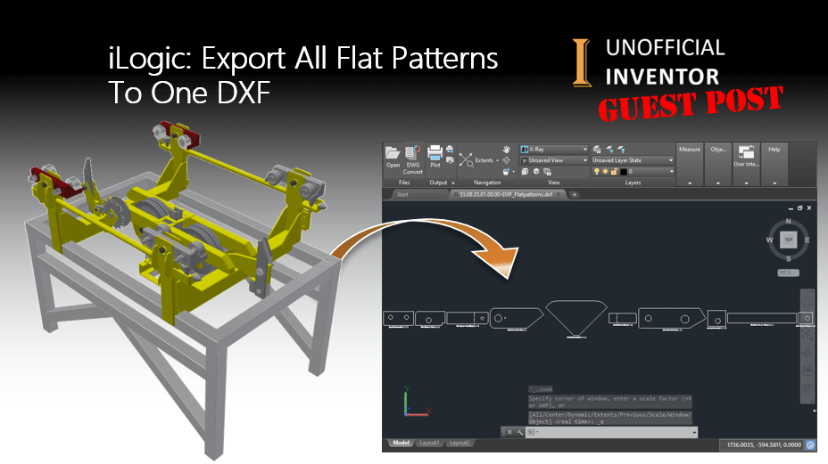
The user had found some code to export all flat patterns from the Sheet Metal components in an assembly to DXF.
What he requested, was the ability to place all flat patterns in the assembly onto a single DXF file.
My solution to this problem is to create a (hidden) drawing document in Inventor, place all the flat pattern views side by side and finally export the flat pattern out to a dxf.
In order to export to dxf with our desired setting (usually you’d want AutoCAD R12 for CNC machining), the first thing we’ll do is to create an .INI file for our export.
To do this, open a drawing document and click “Save Copy As”.
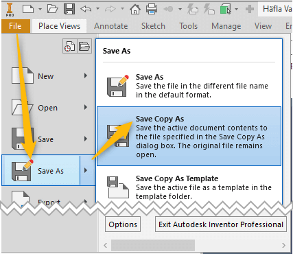
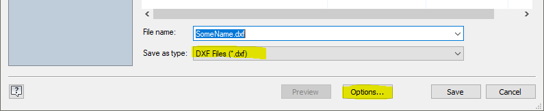
In the “Save as type” dropdown, select DXF and click “Options”.
Set the File Version to “AutoCAD R12/LT 2 DXF” and click “Next”.
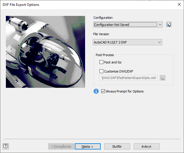
Check the “Model Geometry Only” box and click “Save Configuration…”

Remember where you’ve saved this .INI file (you will need to reference it in the iLogic code). If multiple users will use this rule, save it to a central location where everyone can access it. You can set the path to your INI file by editing “oINI” in the code, as shown below
oINI = "C:\TEMP\DXF EXPORT.ini"
Here is an animated GIF showing the code in action:
Now everything is set up to run the rule.
In the rule you’ll find;
- A sub for the DXF export, using inventors DXF-translator.
- A sub for removing all bend lines in the flat patterns.
- A sub to create a .TXT file, listing the part numbers of the flat patterns from left to right.
- And of course the main sub, looping through all parts in the assembly to find Sheet Metal parts and (create and) place their flat patterns on the drawing.
Since we’re not using any drawing template, it’s very important to set the length units of the drawing document, otherwise the scale will not be accurate in the DXF file. For this I use the UnitsOfMeasure objects from the assembly document and the drawing document.
Here is the iLogic Code:
Sub Main
	'iLogic Code by Jhoel Forshav - originally posted at https://clintbrown.co.uk/ilogic-export-all-flat-patterns-to-one-dxf
	'Check that the active document is an assembly file
	If ThisApplication.ActiveDocument.DocumentType <> kAssemblyDocumentObject Then
		MessageBox.Show("This rule can only run from an Assembly file", "DXF-creator", MessageBoxButtons.OK, MessageBoxIcon.Error)
		Exit Sub
	End If
	'Dim the active document as AssemblyDocument
	Dim oDoc As AssemblyDocument = ThisApplication.ActiveDocument
	'Make sure the assembly is saved
	If oDoc.FullFileName = ""
		MessageBox.Show("Please save the Assembly before running this rule.", "DXF-creator", MessageBoxButtons.OK, MessageBoxIcon.Information)
		Exit Sub
	End If
	'Get the assembly filename without extension
	Dim oAsmName As String = System.IO.Path.GetFileNameWithoutExtension(oDoc.FullFileName)
	'Get the assembly filepath
	Dim oPath As String = System.IO.Path.GetDirectoryName(oDoc.FullFileName)

	'Get the parts only BOM.
	Dim oBOM As BOM = oDoc.ComponentDefinition.BOM
	'Make sure Parts Only is activated
	oBOM.PartsOnlyViewEnabled = True
	'Parts only will be last BomView (difficult to get by name since it's different depending on your language)
	Dim oBOMview As BOMView = oBOM.BOMViews.Item(oBOM.BOMViews.Count)


	'Set a reference to the TransientGeometry object
	Dim oTG As TransientGeometry = ThisApplication.TransientGeometry
	'oX and oY will be used to create points for view placement
	Dim oX As Double = 0
	Dim oY As Double = 0
	'Create the Baseview options to place flatpattern-views
	Dim oBaseViewOptions As NameValueMap
	oBaseViewOptions = ThisApplication.TransientObjects.CreateNameValueMap
	oBaseViewOptions.Add("SheetMetalFoldedModel", False)
	'Set a variable for the drawing document
	Dim oDrawing As DrawingDocument
	'Create a String to return a message if any SM-parts are not saved
	Dim unsavedSmParts As String = ""

	Dim i As Integer = 1
	Dim oInfo As String = ""

	'Traverse Parts Only BOM
	For Each oRow As BOMRow In oBOMview.BOMRows
		Try
			'Get the component definition for the part
			Dim oDef As ComponentDefinition = oRow.ComponentDefinitions(1)
			'Check if the part is SheetMetal
			If TypeOf (oDef) Is SheetMetalComponentDefinition
				'Set a reference to the partdocument
				Dim smPartDoc As PartDocument = oDef.Document
				'Check if the part is saved
				If smPartDoc.FullFileName = "" Then
					If unsavedSmParts = "" Then unsavedSmParts = "The fallowing SM-documents were not saved and therefore " & _
					"no drawingviews were created:" & vbCrLf
					unsavedSmParts = unsavedSmParts & vbCrLf & oDef.Document.DisplayName
					Continue For
				End If
				'Create flatpattern if it doesn't already exist
				If Not oDef.HasFlatPattern
					oDef.Unfold()
					oDef.FlatPattern.ExitEdit()
				End If
				'Create the drawing if it doesn't already exist
				If oDrawing Is Nothing
					oDrawing = ThisApplication.Documents.Add(DocumentTypeEnum.kDrawingDocumentObject, _
					, False)
					'Set the drawings length units to the same as the assemblys length units
					oDrawing.UnitsOfMeasure.LengthUnits = oDoc.UnitsOfMeasure.LengthUnits
				End If

				'Set a reference to the drawing sheet
				Dim oSheet As Sheet = oDrawing.ActiveSheet


				'Create the flatpattern view
				Dim oView As DrawingView = oSheet.DrawingViews.AddBaseView(smPartDoc, oTG.CreatePoint2d(oX, oY), 1 _
				, ViewOrientationTypeEnum.kDefaultViewOrientation, DrawingViewStyleEnum.kHiddenLineRemovedDrawingViewStyle, _
				"FlatPattern", , oBaseViewOptions)

				oView.Name = smPartDoc.DisplayName
				oView.ShowLabel = True

				'Set the position with our oX and oY
				oView.Position = oTG.CreatePoint2d(oView.Position.X + oView.Width / 2, oView.Position.Y)
				'Move oX to place the next view to the right of this one
				oX = oView.Left + oView.Width + 1
				'Remove the bend lines of the view
				RemoveBendLines(oView, oDef.FlatPattern)'You could comment out this line to keep bend lines


				oInfo = oInfo & If (i = 1, "", vbCrLf) & i & ". " & smPartDoc.PropertySets.Item("Design Tracking Properties"). _
				Item("Part Number").Value

				i += 1

				'Close the part
				smPartDoc.Close(True)
			End If
		Catch Ex As Exception
			MsgBox(Ex.Message)
		End Try
	Next
	If oDrawing IsNot Nothing
		'Create the save location string for the DXF
		Dim oDXFName As String = oPath & "\" & oAsmName & "_FlatPatterns.dxf"
		'Save the DXF
		oINI = "" 'Specify your INI file location here (eg C:\TEMP\DXF Export.ini)
		If oINI = "" Then
			MessageBox.Show("You need to specify an INI file location in the code - Look for oINI and set the path", "Error", MessageBoxButtons.OK, MessageBoxIcon.Error)
		End If
		SaveDXF(oDrawing, oDXFName, oINI)
		'Create the save location string for the information txt
		Dim oInfoName As String = oPath & "\" & oAsmName & "_FlatPatterns.txt"
		'Create the txt
		CreateTXT(oInfo, oInfoName)
	End If
	'Close the drawing
	oDrawing.Close


	'return information about any unsaved parts
	If unsavedSmParts <> "" Then _
	MessageBox.Show(unsavedSmParts, "Some parts were not saved", _
	MessageBoxButtons.OK, MessageBoxIcon.Information)
	'Update the assembly (could be dirty if any flatpatterns were created)
	oDoc.Update
End Sub

Sub SaveDXF(oDrawing As DrawingDocument, oFileName As String, oIniFile As String)
	'Set a reference to the DFX translator
	Dim DXFAddIn As TranslatorAddIn
	DXFAddIn = ThisApplication.ApplicationAddIns.ItemById("{C24E3AC4-122E-11D5-8E91-0010B541CD80}")
	'Create translation context
	Dim oContext As TranslationContext = ThisApplication.TransientObjects.CreateTranslationContext
	oContext.Type = IOMechanismEnum.kFileBrowseIOMechanism
	'Create options for the translation
	Dim oOptions As NameValueMap = ThisApplication.TransientObjects.CreateNameValueMap
	'Create a DataMedium object
	Dim oDataMedium As DataMedium = ThisApplication.TransientObjects.CreateDataMedium
	'Set the options (which .ini-file to use)
	If DXFAddIn.HasSaveCopyAsOptions(oDrawing, oContext, oOptions) Then
		oOptions.Value("Export_Acad_IniFile") = oIniFile
	End If
	'Set the filename property of the DataMedium object
	oDataMedium.FileName = oFileName
	Try
		'Try to save the DXF
		DXFAddIn.SaveCopyAs(oDrawing, oContext, oOptions, oDataMedium)
		MessageBox.Show("Dxf saved to: " & oFileName, "DXF SAVED", MessageBoxButtons.OK, MessageBoxIcon.Information)
	Catch
		MessageBox.Show("Couldn't save dxf!", "Error", MessageBoxButtons.OK, MessageBoxIcon.Error)
	End Try
End Sub

Sub RemoveBendLines(oView As DrawingView, oFlattPattern As FlatPattern)
	'Get all the bend edges from the FlatPattern
	Dim oBendEdgesUp As Edges = oFlattPattern.GetEdgesOfType(FlatPatternEdgeTypeEnum.kBendUpFlatPatternEdge)
	Dim oBendEdgesDown As Edges = oFlattPattern.GetEdgesOfType(FlatPatternEdgeTypeEnum.kBendDownFlatPatternEdge)

	For Each oEdge As Edge In oBendEdgesUp
		'Get the curves representing these edges in the drawing view
		For Each oCurve As DrawingCurve In oView.DrawingCurves(oEdge)
			For Each oSegment As DrawingCurveSegment In oCurve.Segments
				'Set visibility to false
				oSegment.Visible = False
			Next
		Next
	Next
	For Each oEdge As Edge In oBendEdgesDown
		For Each oCurve As DrawingCurve In oView.DrawingCurves(oEdge)
			For Each oSegment As DrawingCurveSegment In oCurve.Segments
				oSegment.Visible = False
			Next
		Next
	Next
End Sub

Sub CreateTXT(oText As String, oFileName As String)
	Dim oTxtWriter As System.IO.StreamWriter = System.IO.File.CreateText(oFileName)
	oTxtWriter.WriteLine(oText)
	oTxtWriter.Close()
End Sub
About the Author:
Jhoel Forshav has a Bachelor of Science degree in Mechanical Engineering and a of Master of Science degree in Engineering – Design and Product Development.
He graduated from Linköping University in 2016 and works for a Swedish company that creates industrial steel products. Jhoel’s role at the company is best explained as that of the CAD-expert, automating processes through Addins, iLogic rules and standalone applications for Inventor. Jhoel oversees the CAD procedures and helps manage the Vault.
Jhoel is very active on the Inventor Customization forum and has been an Autodesk Expert Elite member since September 2020.


Great stuff Joel!
Clint: can you show us how you make your GIF animations?
What software do you use?
Thanx!
Hi cadman777, I use Camtasia for Creating videos and GIF’s
Thanx for the speedy reply Clint!
Kind’a pricey program though.
Any ideas what may be cheaper and does the same job?
Hey cadman777, how about using Autodesk screencast (it’s free), you could then use one of the many online mp4 to GIF converters. You would need to download your screencast in MP4 format to achieve this, but it would work well.
Hey Clint, Thanx for the tip. Unfortunately my workstation is permanently offline for security reasons. So if I use screencast, it needs to work offline. Is that possible? Cheers …
Hi cadman777. I’m not sure if it works offline.